Circuit Analysis – Part 4: RC-Filters, LEDs & Buzzers

Before you layout a circuit, it’s generally a good idea to understand what is happening in your schematic.  And before you lay out a schematic, it’s generally a good idea to understand what is happening in your block diagram.

For additional information on circuit analysis, read the previous posts in this series: Part 1Part 2 and Part 3

When a potential difference exists across a resistor, charges move until the potential difference across the resistor is zero. If there is no exit path for the charges, each unit of charge that crosses the resistor decreases the potential difference across the resistor ever so slightly, which then reduces the rate of charge flow. This behavior is what gives RC circuits their characteristic exponential curvature.

RC-Filter

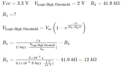
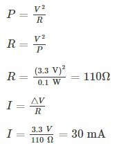
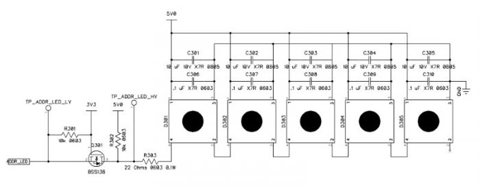
When Switch S1 is closed, R2 is connected directly to ground and R1 is simply generating heat, in that instance, C1 and R2 are the only components of interest in the RC-Filter. When S1 is open, R2 is connected to Vcc through R1, so R1, R2 and C1 must be included in the filter calculations.

Capacitor Selection for RC-Filter

We can pick from a large array of capacitor values. We need something with low equivalent series inductance (ESL) and low equivalent series resistance (ESR) and we need something that is inexpensive. Those conditions all point towards small multilayer ceramic capacitors (MLCC). Since we’re using 0.1 μF ceramics in dozens of spots in the circuit, we might as well use one here. At this point, the choice is arbitrary, not calculated.

The switch datasheet states the settling time is 5 ms (0.005 s). If it was any greater, like the 10-20 ms seen in a relay, we might consider a larger-value capacitor in the 1 µF range.

Our goal is to design an RC circuit that transitions between Vcc and Logic Low in 5ms or greater.

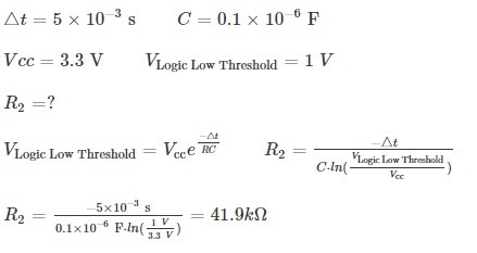
Resistor Selection for RC-Filter During Discharge

And we’d pick a resistor of similar value from the E24-series, or 43 kΩ, with the large tolerances of the capacitors and resistors, it doesn’t make much sense to select a resistor more precise than this.

Pull-Up Resistor

The job of a pull-up resistor is to ensure a digital input is in a defined logic-state when no other circuit elements are acting on the input. When the switch opens, the digital input “Dig” is connected to Vcc through the resistors R1 and R2, so they must both be included in the calculation.

Lower Value Limit Caution

It’s not even close to a problem here, but if higher voltages are in play, a switch has a very low settling time, and a designer chooses a high value capacitance, it’s possible to have high currents flowing through the pull-up resistor.

To choose the lowest allowable value for a resistor, circuit designers should look at the condition where the switch is closed and the net labeled TP is shorted to ground. The current will flow from Vcc to Gnd nets through R1. A very low-value resistor will allow a great deal of current to flow across it. The limits are placed by the energy dissipation of the resistor and the current available from the power supply. Many of these tiny resistors have power dissipation factors of around 1/10 W. Using Ohm’s Law and the Power Law, we can find the resistance and current requirements quickly.

30 mA can easily exceed the recommended power output of some small button-cell batteries. So we’d definitely want a resistor with a value greater than 110 Ω.  Also keep in mind that multiple switches might be depressed at once, causing a large drain on a tiny power supply. In that case, you should decrease the capacitance and increase the resistance to reduce the current through the pull-up resistor.

Each transition can cause electromagnetic noise and trigger the input on an integrated circuit.  Imagine the switch above used in a counting application.  Each switch press might be seen as 10 counts by an integrated circuit.

I think the last time I performed these calculations I was an undergraduate in college some 20 years ago. Most of the time I look for an application example in the datasheet and Ctrl-C Ctrl-V the values into my schematic
Mark Hughes
Royal Circuits Research Analyst

Addressable RGB LEDs

The Addressable RGB LEDs used in this circuit operate off of 5V power rail and 5V logic. While we could probably get away with running them from 3.3V logic, if there is too much ground bounce and Vcc-sag inside the LEDs, we could run into trouble. So a logic-level converter is created out of an N-channel MOSFET. The circuit has a bypass and bulk capacitor for each LED to help reduce noise with the assumption that the LEDS can be placed far from one another. The 0.1 uF capacitor should be placed as close to the LED as possible, with the 10 uF just on the other side of it.

Piezo Buzzer

When crystals are exposed to electric fields, they flex and deform. 

This artistic interpretation of crystalline deformation is from an article on piezoelectrics at AllAboutCircuits.com

By attaching the crystal to a substance that doesn’t flex in the presence of electric fields, differential stresses can be used to cause air molecules to vibrate at audible frequencies.

This animation of a piezoelectric speaker is from an article on piezoelectrics from AllAboutCircuits.com.

Recent Posts

Summit Interconnect Acquires Royal Circuit Solutions and Affiliates

The combination solidifies Summit’s position as one of the largest privately owned printed circuit board (PCB) manufacturers in North America with a  footprint that will now encompass eight manufacturing facilities. The acquisition significantly broadens the scope of Summit’s product offering while expanding the company’s business portfolio of key customers and end-markets. Summit Interconnect is pleased… View Article
Read More

Tech Chat with Thermal Expert, Mike Jouppi

Ever wondered how many vias to use in a thermal package? Or how to route high current traces in small spaces? Good news! Mike Jouppi is back! Check back for a recording of this important PCB resource. In the meantime, feel free to download the Thermal Resistance calculator discussed live.  Download Thermal Resistance Calculator
Read More

Flex PCBS: Design Tips and Material Selection Advice – On-Demand Webinar

In today’s high-tech world, electrical engineers have many choices when it comes to designing their PCBs, including what type of laminate to use. Laminates form the foundation for a high-functioning PCB. In this on-demand webinar, learn how to select the right laminate for your project based on material properties, suppliers, types and more.
Read More

Share

Share on twitter
Share on pinterest
Share on facebook
Or use this public share link