The Reverse Polarity Protection Diode

Incorrectly attaching the power supply leads to a design can instantly ruin countless hours of hard work. Learn how to use Diodes in your designs to keep mistakes from ruining your PCBs!

What is reverse polarity and how does a diode protect it?

Reverse Polarity:

Direct Current power-supplies are designed to establish a potential difference between two or more terminals.  One output is usually called “positive” while another is called “negative” or “ground.” The positive output of a power supply should be connected to the positive input of a circuit, and the negative output of a power supply should be connected to the negative input of a circuit.  Sometimes though, experimenters make mistakes.

The capacitor shown on the left is correctly attached to a battery, while the capacitor on the right is connected in reverse polarity configuration.  Sometimes capacitors will catastrophically fail in this configuration.

Reverse Polarity means that the positive and negative outputs of a power supply have been connected to the wrong terminals on a PCB.  This mistake can cause catastrophic component failure in the form of smoking parts, exploding capacitors, and occasionally an electrical fire.  Fortunately, you can eliminate this risk by adding an inexpensive Schottky diode in series to your design where the power enters the board. This diode should be placed in your schematic and on your PCB immediately after the power connector.

This circuit shows a Schottky Diode (D1) placed on a schematic between the DC Barrel Jack input (J1) and the voltage regulator (U1).  This diode prevents damage in the case of reverse polarity hookup by an experimenter.
A couple of things to keep in mind when selecting a diode for use in your circuit:
  • Choose a Schottky diode if you can.  Schottky diodes have lower voltage drops and are usually better suited for low voltage, low current demand circuits – the kinds of circuits that makers gravitate towards.

  • Choose a diode that it is rated for the voltage and current requirements of your circuit.

  • Choose a surface mount component to keep your assembly cost low.

Use your favorite distributor to search for “Diode Schottky” or “Diode Rectifier” then drill down to select a diode that is rated for or exceeds the voltage and current requirements of your circuit.  

This screen capture from a major distributor shows just a few of the options available for your project.

If you have trouble finding a diode that suits your needs, remove the term “Schottky” from your search – you’ll find more parts, but lose up to 0.7 V across the diode.

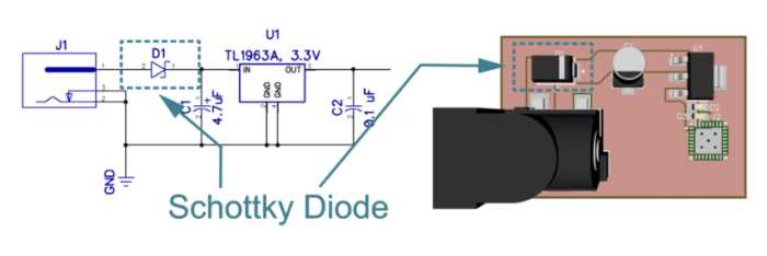
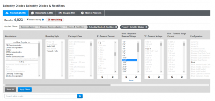
For example, if your power supply provides 12 V at 0.7 A of current, you may wish to select a diode that has a reverse breakdown voltage of 15V and 1A of forward current.  You select the voltage based on the maximum voltage of your power supply and  and you choose the current rating based upon the needs of your circuit.  If you exceed the current or voltage rating of your diode, you will damage it.[1] [2] 

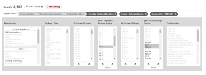
Most of today’s maker circuits involve Arduinos, Raspberry Pi’s, BeagleBones, and similar devices.  Most of these devices operate in the 3.3 V – 5 V range, requiring less than 100 mA of current.  For that purpose, a 30V @ 200 mA Schottky should more than suffice – and at less than a nickel a part to provide electrical safety to your board, it is difficult to argue against including one in your design.

This screen capture from a major distributor shows another option. Visit Mouser or Digikey to try it for yourself.

If you have trouble finding a diode that suits your needs, remove the term “Schottky” from your search – you’ll find more parts, but lose up to 0.7 V across the diode.

This article was originally published by PCBLayout.com, offering design review and PCB layout services in minutes. 

Recent Posts

Summit Interconnect Acquires Royal Circuit Solutions and Affiliates

The combination solidifies Summit’s position as one of the largest privately owned printed circuit board (PCB) manufacturers in North America with a  footprint that will now encompass eight manufacturing facilities. The acquisition significantly broadens the scope of Summit’s product offering while expanding the company’s business portfolio of key customers and end-markets. Summit Interconnect is pleased… View Article
Read More

Tech Chat with Thermal Expert, Mike Jouppi

Ever wondered how many vias to use in a thermal package? Or how to route high current traces in small spaces? Good news! Mike Jouppi is back! Check back for a recording of this important PCB resource. In the meantime, feel free to download the Thermal Resistance calculator discussed live.  Download Thermal Resistance Calculator
Read More

Flex PCBS: Design Tips and Material Selection Advice – On-Demand Webinar

In today’s high-tech world, electrical engineers have many choices when it comes to designing their PCBs, including what type of laminate to use. Laminates form the foundation for a high-functioning PCB. In this on-demand webinar, learn how to select the right laminate for your project based on material properties, suppliers, types and more.
Read More

Share

Share on twitter
Share on pinterest
Share on facebook
Or use this public share link