Understanding Electroplating and Etching

Good engineers become great engineers when they have a comprehensive understanding of how printed circuit boards are made.  This quick tip covers electroplating, via formation, and etching.

  1. Fabricators will start with a copper-clad core or stack.
  2. They then drill holes in the panel that are larger than the engineer specifies — these holes will become smaller after electroplating.
  3. The next step is to cover the entire panel with a photo-imagable mask. This material hardens when exposed to light.
  4. The artwork is either projected on the panel or imaged with a line-scan laser. The light selectively hardens the material in certain areas.
  5. The mask material that was not exposed to light is then washed away.
  6. The entire panel is connected to the cathode of a pulsed-DC power supply. Copper ions leave a sacrificial ingot and deposit on the panel in the exposed areas.
  7. All of the mask is washed away, leaving a panel with exposed copper that is raised in certain areas that will become the traces, pads, and copper pours.
  8. The entire panel is placed in an etching solution that removes copper from the entire board. The parts that have thickened in the electroplating process take longer to etch, so if the board is removed at the right time, all that will be left behind are traces atop a dielectric substrate.

If you have any further questions, contact our engineering experts for more information.

Recent Posts

Summit Interconnect Acquires Royal Circuit Solutions and Affiliates

The combination solidifies Summit’s position as one of the largest privately owned printed circuit board (PCB) manufacturers in North America with a  footprint that will now encompass eight manufacturing facilities. The acquisition significantly broadens the scope of Summit’s product offering while expanding the company’s business portfolio of key customers and end-markets. Summit Interconnect is pleased… View Article
Read More

Tech Chat with Thermal Expert, Mike Jouppi

Ever wondered how many vias to use in a thermal package? Or how to route high current traces in small spaces? Good news! Mike Jouppi is back! Check back for a recording of this important PCB resource. In the meantime, feel free to download the Thermal Resistance calculator discussed live.  Download Thermal Resistance Calculator
Read More

Flex PCBS: Design Tips and Material Selection Advice – On-Demand Webinar

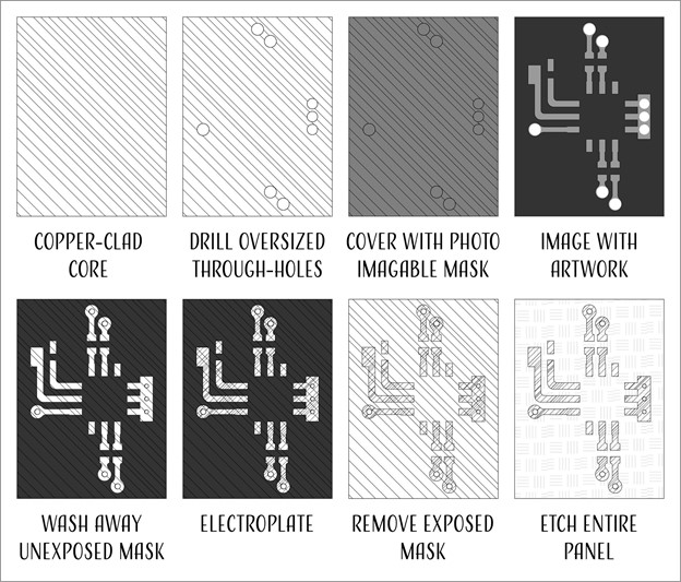
In today’s high-tech world, electrical engineers have many choices when it comes to designing their PCBs, including what type of laminate to use. Laminates form the foundation for a high-functioning PCB. In this on-demand webinar, learn how to select the right laminate for your project based on material properties, suppliers, types and more.
Read More

Share

Share on twitter
Share on pinterest
Share on facebook
Or use this public share link