Before you layout a circuit, it’s generally a good idea to understand what is happening in your schematic. And before you lay out a schematic, it’s generally a good idea to understand what is happening in your block diagram.
For more details read previous posts: Circuit Analysis – Part 1 and Circuit Analysis – Part 2.
IMU Sensor
The BNO055 inertial measurement unit by Bosch has three types of tri-axial sensors: Accelerometer, Gyroscope, and Magnetometer. To increase accuracy, a 32.768 kHz MEMS oscillator is included and must be enabled via register flags.
The datasheet notes that the sensor’s sensitive magnetometer should be mounted well away from any ferromagnetic materials. Place this device as far away from the LCD, header pins, badge clips, and batteries as possible. One other thing — the sensor package is rather inaccurate before calibration. Be sure to follow the Bosch calibration guidelines before using your device.
Environmental Sensor
Of all the integrated circuits on a board, this is perhaps the easiest one to implement. Simply place one decoupling capacitor at one pin and one decoupling capacitor at another pin. Communication is via I²C, and should be relatively easy to implement.
Real-Time Clocks
Real Time Clocks (RTC) are designed to keep track of seconds, minutes, hours, days, months, and years using an accurate clock source and a small power source. Some even include interrupts that can bring a microcontroller out of sleep at a particular time to perform a task.
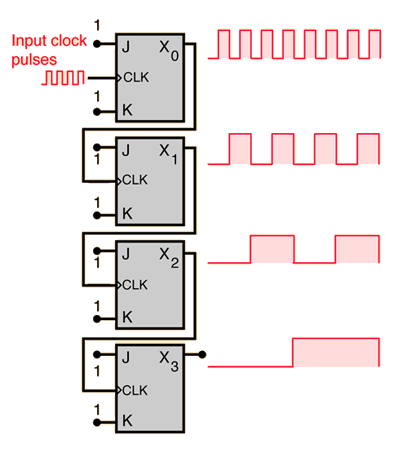
The clock source is 32.768 kHz. Why such a seemingly odd value across all devices? It makes sense when you think about 32.768 Hz in binary. 215 is equivalent to B1000000000000000.

The RTC circuit detects the transitions of the oscillator, and a series of flip-flops on the die go to work successively dividing the signal 15 times, until the final stage of the circuit keeps track of seconds.

That makes sense, but why 215 instead of 214 or 216? That likely harkens back to the days of digital watches. 215 was good enough to keep time within a minute per month. Each additional gate costs money to fabricate on an ASIC, so the watch/clock industry settled on “good enough.” It’s possible to purchase crystals at 65.536 kHz (216) and 131.072 kHz (217), but you’d need additional divider stages to work properly.

Input Switches
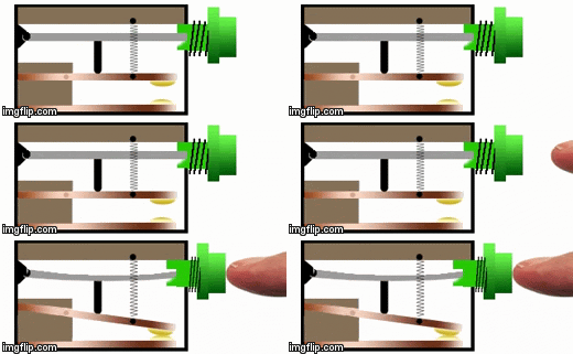
We often think of switches as simple devices that exist in one of two states: on or off, open or closed. And in the steady-state, long after a transition, that is how they behave. But during the transition between states, many switches tend to misbehave as their contact points make and break contact several or even dozens of times.

It has to do with the way switches are designed. Many switches are designed with springs, compliant mechanisms, or “snap-action” mechanisms that mechanically hold the switch element in place on contacts Like a ball bouncing on the ground, the contact elements often bounce immediately after the transition. So instead of a single transition between states, there can be dozens of transitions back and forth and back again.

Each transition can cause electromagnetic noise and trigger the input on an integrated circuit. Imagine the switch above used in a counting application. Each switch press might be seen as 10 counts by an integrated circuit.
Switch Debouncing
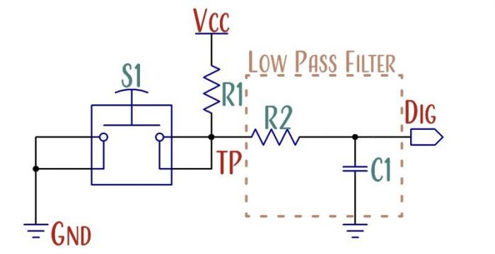
We’re electrical engineers, not mechanical engineers. So we have no control over the switch design, and cannot control the bounce. We just have to deal with it. Our two options are to design an electric circuit to deal with the bounce or write software code to deal with the bounce. Datasheets sometimes recommend different debounce circuits or no debounce at all.

The next blog explains the calculations for the circuit.


